Background
Recently we were consulted by the team developing the Observatory Visualization Tool (OVT) for the James Webb Space Telescope (JWST). The OVT is a web-based application that allows users to observe the JWST during its various deployment phases in real-time, while also providing the capability to play back historical data for analysis. We implemented the animations for the moving parts of JWST so that its telemetry data can be used to represent the current state of the telescope. This included cloth animations for its Sunshield. Cesium provided the ideal fit for the team’s requirements, which at a high level included support for 3D visualization, an earth-centered inertial coordinate frame, and a document-driven playback capability (CZML). Cesium was designed for dynamic data, and 3D data can be easily animated with the timeline. This post describes how we created 3D animations that run independently of the timeline.
The Problem
One of our first tasks was integrating 3D assets and animations for the JWST into Cesium. Cesium’s support for glTF models and animations made this fairly easy, but when we started dealing with our real-time data we ran into a few issues. The system needed complete control over the various deployment animations (see video for reference). Ideally we wanted to let the system dictate animation playback via normalized time expressed as a value between 0.0 and 1.0. This way the system could simply send a single value and manage the logic of whether an animation should play forwards, backwards, pause, reset, etc.
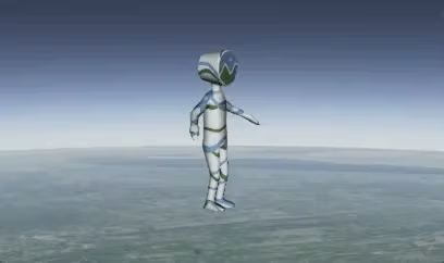
At the time of writing this blog, Cesium provides a robust animation capability with ModelAnimationCollection, but these animations are driven exclusively by the timeline. We still needed some API to specify the current frame or playback time for a given animation. Luckily, Cesium makes programmable animation possible through the use of ModelGraphics.nodeTransformations. Node transformations allow you to manually specify the translation, rotation, or scale of a given model node in the node’s local space. We experimented with node transformations early on in the project and found them useful for simple animations or effects where we did not want to burden the artist with animating a single node such as a blinking light or a thruster. The following animation shows Cesium man bobbing his head to a custom animation with node transformations.
Finding a Solution
Rather than start from scratch, we decided to see if it was possible to build an animation system that utilized node transformations. We first needed to get a hold of the animation data itself as well as the original node hierarchy since node transformations do not store any of the relationship data. I ended up writing a simple parser that takes a glTF in binary format (.glb) and extracts the node hierarchy (each node has a pointer to its parent) and animations. It then stores them in an object called an AnimationSet. Each animation in the set maintains a map of AnimationTracks, which store the AnimationKeys for a given node name. AnimationSets are then associated with an AnimationPlayer, which is where all of the real magic happens. In order to perform the actual animation logic, the code iterates over the nodes’ tracks and finds the keys to “tween” based on the current playback time. The key frame values are then computed or interpolated for each component of a node’s transform: translation, rotation, and scale.
Once the implementation was complete, I was quite excited to try it out. I wrote a quick sample app and downloaded this construction worker model (we’ll call him Mike) to use as my trial mesh. In my experience, skinned animated meshes tend to be about as complex as things get, so it seemed like a good test case.
However, this is what I saw when I tried to play the “walk” animation for Mike…

The Devil Is Always In The Details
I was confused by what I was seeing. What portion of the animation code was failing? I decided to invest a little time writing some tools to help me debug. I wanted to be able to visualize how the nodes were oriented before trying to triage certain sections of code. Cesium’s DebugModelMatrixPrimitive made this pretty easy. All I had to do was calculate the world-space transform of a given node. Granted, this is a fairly expensive operation as it requires performing calculations up the entire hierarchy for a given node, but for debugging purposes this was OK with us. A nice side effect of adding the ability to visualize a node’s transform was that it helped us identify rigging and export issues from our content creation tool as well.
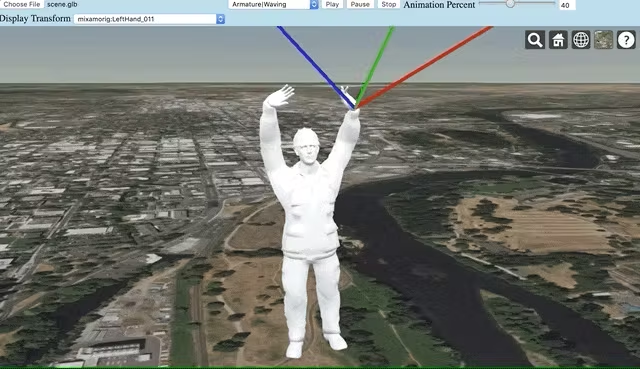
I decided to take a look at a node that I knew rotated on only one axis according to the glTF data. I noticed something very odd when it started to animate. It was rotating on its local x-axis instead of the parent node’s x-axis as I was expecting! glTF animation data always expresses node transforms relative to their parents. CesiumModelGraphics.nodeTransformations, however, are expressed relative to the node’s own local coordinate frame.
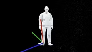
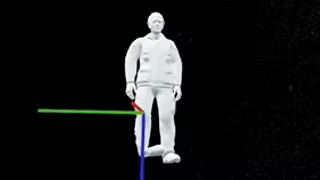
Rotating the right foot about the x-axis (red) in local space (above) and the parent node’s space (below).
Revisiting The Solution
So, how do we take something expressed in a node’s parent coordinate frame and convert it to something expressed in the node’s local frame? Handling the scale component is fairly straightforward, since scale happens before all other components are combined in the final transformation matrix (according to the glTF 2.0 spec), we can assume this still happens in local space. We still need to take into account the fact that the scale value is expressed in absolute terms in the animation data but the scale we express in the Cesium node transformation is relative to the original scale. In other words, if a node’s original scale in a glTF model is 2.0 for each xyz component, then setting the node transformation scale value to 2.0 in Cesium will result in a node that appears to be at an absolute scale of 4.0. Therefore, we need to divide the interpolated scale value by the original value from the glTF model file. This “relativity” needs to be accounted for during the translation and rotation computations too.
The translation component is a little more complicated. We need to multiply the interpolated animation value by the inverse matrix of the node’s original rotation from the glTF data. This gives us the translation expressed in the node’s local coordinate frame. This inverse matrix is also necessary for calculating the animated rotation, which is the most complicated of the three transformation components. After calculating the “slerped” result between the two current rotation keyframes, we extract the axis from the quaternion and multiply it by the inverse matrix. The axis of the rotation is expressed in local node space at this point. The axis is then recombined with the angle to form the final rotation quaternion.
Conclusion
If your head is spinning from all of this math, take comfort in the fact that mine was too by this point! After refactoring the animation code, I loaded Mike back up, held my breath as I hit the play button, and…voila! We finally had timeline independent animation happening within Cesium.
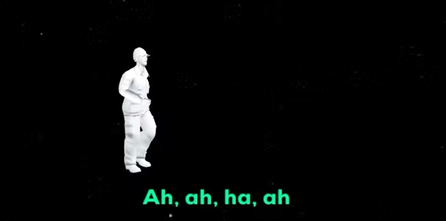
The code for the animation player is free to use. Please feel free to submit issues or pull requests as I’m sure there are still improvements that can be made to the system. A live version of the sample application as well as the source code for it can be located here. Take it for a spin and try out your own models. We would love to hear if anyone from the Cesium community finds this work useful, so feel free to get in touch via Twitter or email!